Netlist Rules and Examples
The MINT/netlist file is a plain text file that has the extension '.uf' (eg. device.uf).
The basic structure of the netlist as follows:
- (Optional) Import the modules you will need to use in the design.
- Declare the type of device and the device name.
- (Optional) Instantiate the imported modules.
- Declare each layer present in the device.
- Within each layer declare the components and channels on that layer.
- (Optional) Within each layer, set the position of the components in that layer.
Summary of the basic MINT device structure
#Single Comments start with '#' symbol. There is no current support for multiline comments

IMPORT nameofdevicetoimport

DEVICE nameofthisdevice

nameofdevicetoimport instance1, instance2, .... ;

LAYER FLOW

...

END LAYER

LAYER CONTROL

...

END LAYER
Note: The full example in text is given right after this tutorial.

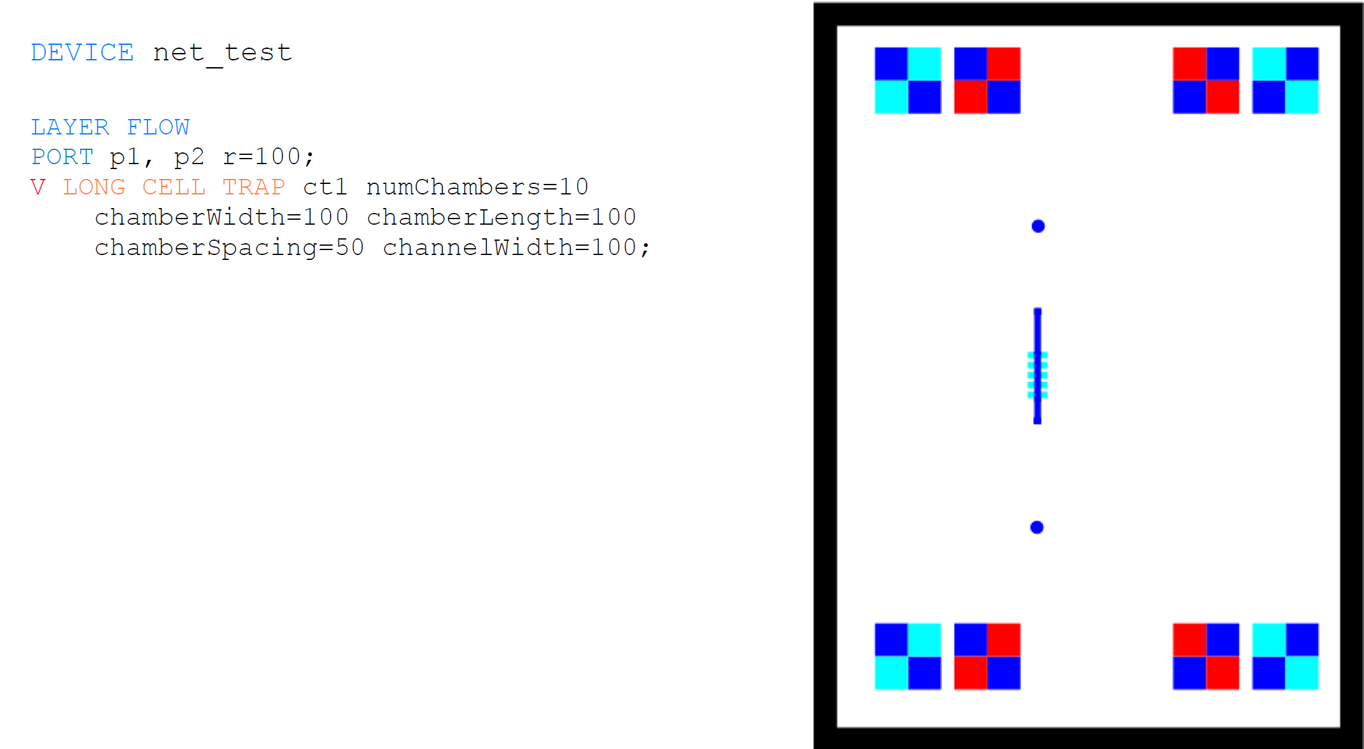
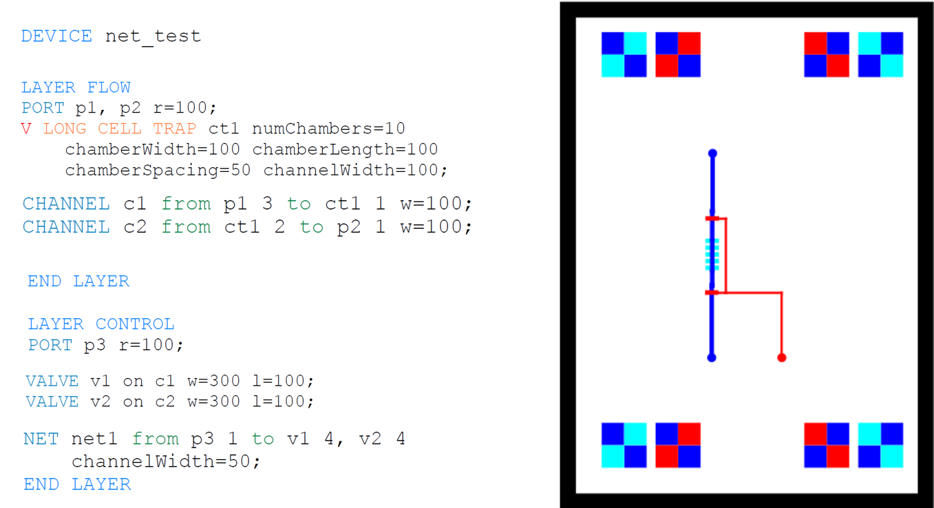
DEVICE net_test
LAYER FLOW
PORT p1, p2 r=100;
V LONG CELL TRAP ct1 numChambers=10 chamberWidth=100 chamberLength=100 chamberSpacing=50 channelWidth=100;
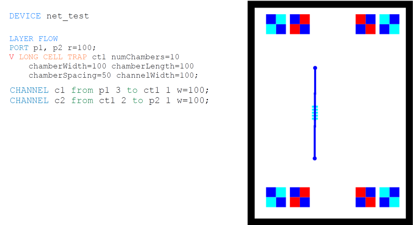
CHANNEL c1 from p1 3 to ct1 1 w=100;
CHANNEL c2 from ct1 2 to p2 1 w=100;
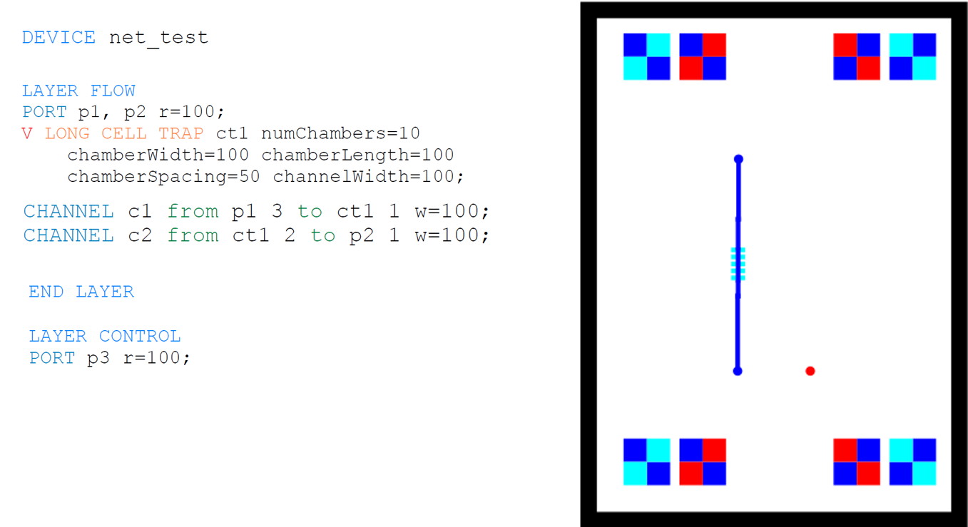
END LAYER
LAYER CONTROL
PORT p3 r=100;
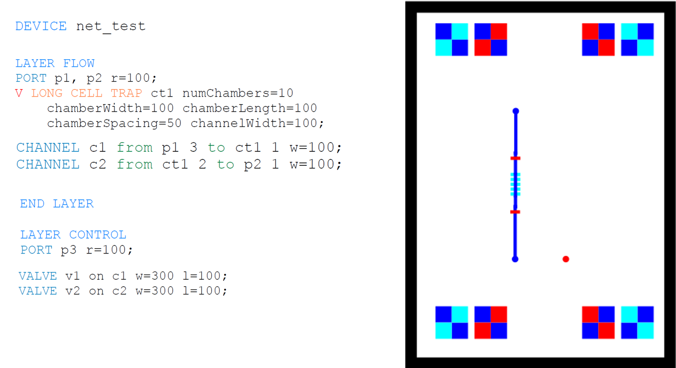
VALVE v1 on c1 w=300 l=100;
VALVE v2 on c2 w=300 l=100;
NET net1 from p3 1 to v1 4, v2 4 channelWidth=50;
END LAYER
MINT allows the designer to fix the position of a component through the SET statement.
Syntax
ufname SET X INT Y INT